
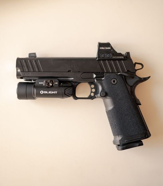
An optic that is "almost right" is usually expensive proof that almost means wrong.
A milled slide on the bench, calipers nearby, and a row of optic photos open on screen—this is where costly guessing starts. Two footprints can look nearly identical until the screws miss by a fraction, the recoil bosses sit in the wrong place, or the optic rocks because the pocket depth is off. Close is not compatibility; it is stripped threads, ugly gaps, and return shipping.
The useful question is not which brand the cut resembles at first glance. The real job is identifying the mounting interface: screw pattern, recoil-lug shape, pocket length and width, and the front or rear indexing surfaces that actually locate the optic. Once that interface is known, the market stops looking chaotic and turns into a short list of models that truly fit.
- Adapter plates and filler plates can disguise the original cut.
- Some slides borrow one footprint's screw spacing but another's recoil-boss geometry.
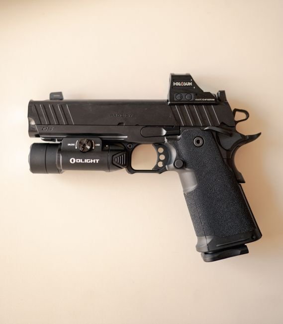
Getting the slide cut right is the foundation of the whole fitment process — once you know whether the pocket is a direct mill or a plate host, you can measure screw spacing, boss location, and pocket depth with confidence instead of guessing from photos alone.
Three names, three different jobs
Optic footprint
The footprint is the pattern on the optic itself: screw spacing, recoil sockets, bosses, and underside geometry. It describes what the sight expects to sit on, not what is already cut into the slide.
Slide cut
The slide cut is the pocket machined into the slide. In a direct-mill setup, that pocket must match the optic’s support geometry, not merely its screw holes.
Plate system
A plate system adds an adapter between slide and optic. The slide interfaces with the plate first; the plate then recreates the optic’s footprint.
Screw pattern
Matching hole spacing answers only one question. Lugs, ledges, depth, and radius control recoil support and often break supposed matches.
First identify whether the slide is direct-milled or plate-based. That fork decides which surfaces matter first.
A direct-milled slide must support the optic itself. A plate-based slide supports the plate, and the plate supports the optic. For a quick refresher on how red dot sights work, remember that recoil is carried by bearing surfaces, not screws alone.
Identify the host before naming the cut
-
Look for a removable plate
A visible plate seam, cover plate, or separate fasteners usually means the slide is only a host. In that setup, the optic does not mate directly to the slide pocket.
-
Find where the recoil lugs live
If the locating bosses or indexing posts are part of a detachable plate, the relevant interface is the plate system. The slide cut underneath is not yet the optic footprint.
-
Ignore the marketing label for a moment
Terms like MOS, OR, and optic-ready often describe a mounting ecosystem rather than the actual optic pattern cut into metal.
-
Reserve “direct mill” for true slide contact
A direct-milled slide has the optic seated against the slide itself, with screw holes and recoil surfaces machined into that pocket.
-
Make the footprint guess only after that
Once host type is clear, screw spacing, lug geometry, and pocket dimensions can be compared without mixing plate standards with optic standards.
A slide marked MOS may simply accept a family of adapter plates. That is why Glock 19 MOS optic options can cover several different footprints.
A common mistake is treating the host label as proof of an RMR, Docter, or other direct pattern. The real interface may be one layer higher: slide to plate, then plate to optic.
Use the cut’s geometry to narrow it down fast
-
Count the recoil bosses first
Two front bosses, four corner lugs, or no true bosses at all eliminates many families immediately. Their spacing matters as much as their number: closely paired front lugs suggest one group, while widely set corner lugs point to another.
-
Read the side walls and front wall
Some cuts have straight, boxy walls; others taper, radius, or leave reliefs around the corners. A tall front wall with shallow side support usually indicates a different pattern than a cut with deeper side engagement and a more open nose.
-
Check screw-hole placement, not just spacing
Hole location relative to the bosses is a high-signal clue. Screws placed behind the recoil lugs, between them, or far to the rear often separate footprints that otherwise look similar in photos.
-
Estimate pocket depth and floor features
A deep pocket with clear indexing shelves is rarely confused with a shallow plate host. Machined pockets for sealing plates, posts, or battery clearance can also distinguish near-lookalikes.
-
Inspect the rear profile
The back edge often settles the debate: square rear shoulder, rounded corners, stepped relief, or a long rear overhang each narrows the field quickly. Rear geometry is especially useful when screw dimensions are still unknown.
When two candidates still remain, dimensions confirm what geometry strongly suggests.
Use a measurement set, not a single match
A dependable identification usually comes from several dimensions checked together, not one lucky match. The most useful set is small:
- Screw-hole spacing measured center to center
- Pocket length front to rear
- Pocket width at the true bearing surfaces, not chamfers
- Boss or recoil-lug size and location relative to the screws
One shared number can mislead. Many cuts have very similar screw spacing, yet differ in lug placement, hole offset, sidewall shape, or pocket depth. Others share overall length while changing the surfaces that actually stop recoil.
That is why an optic may seem to “fit” at first glance but still rock, bind, sit proud, or leave the screws absorbing forces they were not meant to carry.
The reliable approach is to compare at least three dimensions, then verify them against a manufacturer drawing or a reputable footprint reference. When sources disagree, the slide maker’s print and the optic maker’s print carry more weight than retailer listings or forum diagrams.
Decorative bevels, coatings, and radiused corners can distort readings. Measurements taken from the wrong edge often create false matches between otherwise incompatible cuts.
Lookalikes that still misfit
Aligned screw holes confirm only part of the interface.
A wrong cut can let the optic rest on screw heads, corner radii, or one edge instead of the recoil bosses. It may feel tight at the bench, then shift under recoil and load the screws instead of the cut.
Many share the basic pattern, but seating details still vary.
Some cuts use bosses, wall relief, or pocket depth that suit one housing better than another. That is why RMR and 507C fit differences can matter even when the screws line up.
Docter/Noblex, FastFire, Venom, RMSc, and K-style optics often create false confidence.
Several families overlap in length or screw spacing, yet differ in lug location, rear shelf shape, and edge geometry. A dot can bolt down while having little or no real recoil support.
A bad match often passes a quick visual check. Common clues are rocking before torque, daylight under one edge, witness marks on screws rather than lugs, or a housing that must be forced into the pocket.
Confirm with source drawings
Quick visual recognition is only a first pass. Final confirmation comes from original-source documents: the slide maker’s optics-cut print, the optic maker’s footprint drawing, and any plate manufacturer fit chart tied to a specific revision. A factory dimensioned drawing carries more weight than marketing photos, retailer copy, or forum lists.
The key cross-check is simple: match screw specification, recoil interface, and pocket envelope across those sources. Revision notes matter. Some makers keep the same product name while changing boss height, screw depth, or pocket length.
Record the geometry when the cut is nonstandard
When a slide has been custom milled, altered, repaired, refinished, or worn, pattern names become less useful than exact measurements. At that point, the goal is to capture geometry that another machinist, plate maker, or optic manufacturer can verify.
Document at least:
- Screw-hole center spacing and thread size or pitch, if known
- Pocket length, width, and depth, measured at more than one point
- Boss or lug shape, height, spacing, and distance from pocket edges
- Wall angles, radii, chamfers, and relief cuts
- Square-on photos of the pocket plus side-profile images showing depth and screw engagement
- Any signs of welding, elongation, peening, corrosion, or stripped threads
That record turns an unknown cut into a usable fitment dataset, even when factory cues are gone.
- Check host Plate system or direct mill first.
- Match geometry Screws, lugs, pocket, and rear edge must agree.
- No pressure If it rocks, gaps, or needs persuasion, it is wrong.
- Verify first After fit is confirmed, then check screws and torque.
Any need to press, file, elongate holes, or “make it work” is a stop signal. Uncertainty means pause, confirm against drawings or the maker, then address screws, sealing plate, and torque.
Frequently Asked Questions
How do I know if my slide is direct-milled or uses a plate system?
Look for a removable plate seam or separate fasteners. If recoil lugs are part of a detachable plate, the relevant interface is the plate system, not the slide pocket itself.
Is matching screw-hole spacing enough to confirm a fit?
No. Aligned screw holes confirm only part of the interface. The optic could still rest on the wrong surfaces instead of the recoil bosses.
Do all RMR-family footprints interchange?
Not always. Many share the basic screw pattern, but bosses, wall relief, and pocket depth can still vary between housings.
What should I do if a slide cut is custom or nonstandard?
Document exact measurements: screw spacing, pocket length/width/depth, boss shape and location, and wall angles, then verify against source drawings.
What are the warning signs of a wrong-fit optic mount?
Rocking before torque, daylight under one edge, witness marks on screws instead of lugs, or needing to force the housing into the pocket.
A reliable stop/go check is simple: identify the host, match the full geometry, and reject any setup that does not sit flush without effort. When the fit is not certain, verification comes before hardware details.



8 Comments
Step 3-ish — the “identify the host before naming the cut” part — is where I got stuck.
My slide is labeled MOS-style by the seller, but when I pulled the plate off I still couldn’t tell if I was looking at a true direct mill or just a plate host with weird geometry. The screw holes seem to match one pattern, but the rear edge and bosses don’t line up with the drawings I found. Is that basically the false-positive situation you mentioned, where shared screw spacing tricks you into the wrong ID?
Yes, that’s exactly the kind of false positive I was warning about. “MOS-style” often describes the adapter system more than the actual optic interface, so the first question is whether the optic would seat directly in the slide or only via a plate.
If the slide has a removable plate and the optic never contacts a full direct-mill pocket, treat it as a plate host first. Then identify the plate interface separately from the optic footprint. Screw-hole spacing alone isn’t enough if the bosses, wall shape, or rear indexing edge disagree with the drawing.
I ran into the same thing on a clone slide. The holes looked right, so I assumed I was good… nope. Sat proud in the back and rocked under pressure.
Once I checked the pocket depth and where the lugs were actually supporting recoil, it was obvious the “match” wasn’t really a match.
The lookalikes section was my favorite because wow, the internet makes everything sound interchangeable when it’s really not.
I had two cuts with basically the same screw spacing on paper, and one still misfit because the indexing surfaces were different. So yeah, this worked for me — using the whole measurement set instead of chasing one number finally got me to the right footprint name.
Good article, but I wish there was even more emphasis on measurement tolerances.
A lot of people read “measure screw spacing” and think one caliper reading solves the mystery. In real life, if the pocket length/width and lug location aren’t all checked together, you’re still guessing. I learned that the annoying way after trying to make a near-match fit. It technically bolted down, but it definitely was not seating flush, which your stop/go check calls out.
Honestly the “hardware details last” reminder is probably the most important line here. People love to argue screw length before they’ve even confirmed the cut geometry.
Totally agree. A single shared dimension creates a lot of confidence for something that may still be wrong in three other ways.
If an optic only “kind of” fits, that’s usually the signal to stop and re-check the full geometry against a source drawing. Flush seating and proper recoil support matter more than whether the screws can be persuaded to pull it down.
“People love to argue screw length before they’ve even confirmed the cut geometry” lol, painfully accurate.
I’ve watched friends do exactly that and then wonder why the optic shifts later.
This actually helped a lot. I was about to order an optic based purely on the “looks like RMR” method 🙃 but the part about footprint vs slide cut vs plate system stopped me.
Checked the host first, measured the pocket and screw spacing together, and yep… not what I thought it was. Saved me from buying the wrong plate.