
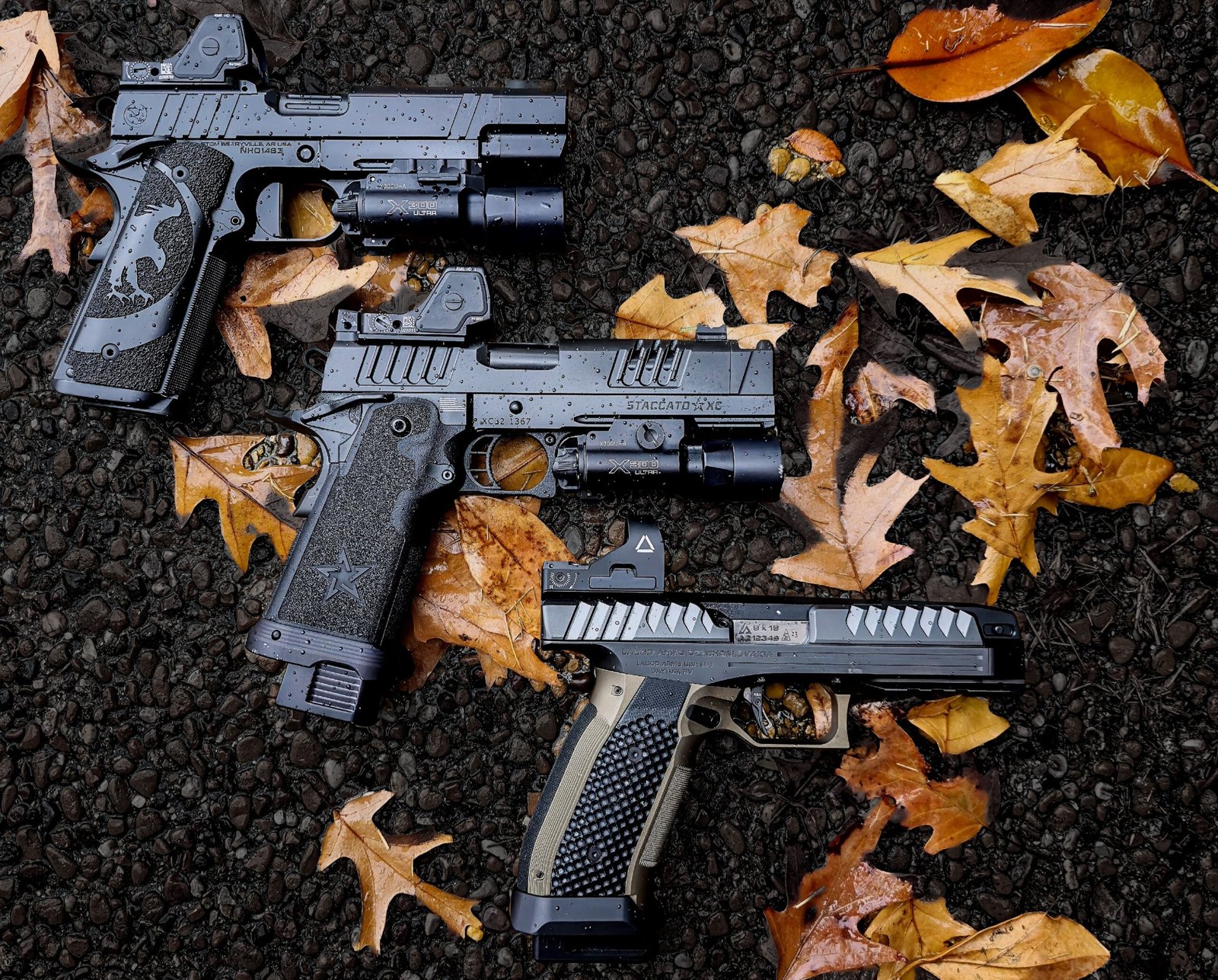
A screw can feel solid at the bench and still let an optic walk under recoil.
A red-dot mount that appears secure can be under-clamped, allowing minute movement that shifts zero over repeated firing. The opposite error is equally damaging: excessive torque can stretch or snap a small screw, strip the slide or mount threads, crush a thin optic housing, or distort the mounting interface.
Finger feel is a poor gauge at this scale. Fastener size, thread pitch, screw material, coating, mount geometry, and the presence of threadlocker all change the usable torque range. The reliable value is therefore the one specified by the optic, mounting-plate, or pistol manufacturer for that exact interface. When instructions conflict, the component maker’s guidance for the relevant screw and mounting arrangement is the controlling reference; a calibrated inch-pound torque driver makes that specification repeatable.
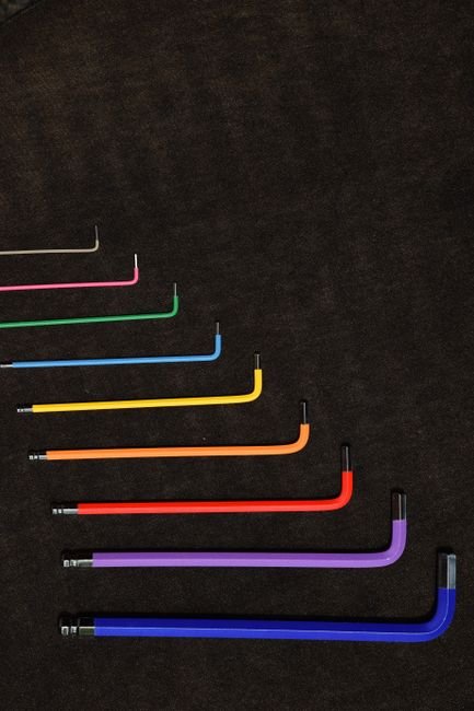
Getting red dot screw torque right means following the exact specification for that optic, plate, and slide stack, since finger feel alone cannot tell safe clamp load from a stripped thread at this scale.
Use the torque for the complete mounting stack
For many pistol-mounted red dots, the final screw torque falls in the low-teens inch-pound range. That is a useful starting orientation—not a universal setting. A screw that is correct at 12 in-lb in one installation can be under-tightened or destructive in another.
The controlling value comes from the complete stack: optic manufacturer, mounting plate or adapter manufacturer, slide or direct-mount cut, and the specific screws supplied or approved for that arrangement. Follow the most specific compatible instruction, particularly where a plate maker limits torque below the optic maker’s general recommendation.
Several details can change the allowable load:
- Thread engagement: shallow engagement needs restraint; bottoming a screw can mimic proper clamp force.
- Screw size and material: small 6-32, M3, and M4 fasteners do not share one torque value.
- Plate interfaces: recoil lugs may carry shear load, while screws mainly provide clamping force.
- Threadlocker and lubrication: both alter the relationship between applied torque and actual clamp load.
If specifications conflict or are absent, the firearm, optic, and mount makers are the reliable source—not a generic torque chart.
Treat each screw joint separately
A pistol optic can contain three distinct screw joints, and they are not interchangeable. Before selecting hardware, identify the slide cut and its mounting interface; screw length, thread pitch, and bearing surfaces follow from that geometry.
- Direct-to-slide screws clamp the optic body to the slide. Their usable engagement is limited by slide thread depth and by anything protruding beneath the optic.
- Optic-to-plate screws fasten the sight to an adapter plate. These are often shorter and may use a different head style or thread than the slide screws.
- Plate-to-slide screws secure the adapter itself. They carry the plate’s recoil load and may have a separate torque specification.
Torque only develops clamp load in a correctly fitted joint. The optic or plate must sit fully on its locating surfaces, while recoil lugs, bosses, or cross slots engage their matching pockets without rocking. A gap, wrong screw length, or incomplete lug engagement cannot be corrected by tightening harder; extra torque can strip threads, deform the optic, or create a false zero that shifts under recoil.
Verify the Fasteners and the Mating Surfaces
-
Match the approved screw
Confirm diameter, thread pitch, head style, and specified engagement for that optic/plate/slide stack. A screw can fit the hole yet be too long, too short, or wrong under the head.
-
Inspect every screw
Reject damaged threads, rounded drive recesses, distorted heads, or old threadlocker buildup. Reused screws are only suitable when the manufacturer permits reuse and their condition is sound.
-
Clean and dry the threads
Remove oil, debris, and cured threadlocker from both male and female threads. Contamination changes friction, making torque readings less meaningful.
-
Seat the optic before tightening
Ensure the optic sits flat, recoil lugs are fully engaged, and no cable, gasket, burr, or trapped debris holds it proud of the surface.
-
Check for bottoming or interference
A screw that contacts the bottom of a blind hole, internal slide feature, or extractor-related clearance can feel tight without clamping the optic. Confirm that tightening draws the optic down rather than merely stopping the screw.
If screw length is uncertain, compare it with the mounting-system documentation rather than trimming or substituting by appearance.
A torque wrench only reports resistance at the driver. It cannot distinguish proper joint preload from a screw bottomed in its hole, a head bearing incorrectly, or debris compressed beneath the optic. Flat contact and correct screw geometry must exist before torque has meaning.
Prepare the threads before adding any threadlocker
- Remove old residue completely
Old adhesive, oil, solvent, and metal debris can produce misleading torque readings. Clean the screw and tapped hole with a residue-free method, then allow both to dry fully.
- Identify a pre-applied locking patch
A dry patch on new screws is already a locking system. It is not a cue to add liquid threadlocker; many patches are intended for a single installation cycle.
- Use liquid only when the mount maker approves it
Apply the specified removable product sparingly to the engaged screw threads, not into the hole. Formula matters: an unapproved high-strength compound can complicate later service or conflict with the manufacturer’s instructions.
- Avoid filling blind holes
Liquid trapped at the bottom of a hole can create hydraulic resistance as the screw advances. That resistance may feel like correct clamp load while the screw is not seated, and excess can migrate onto the optic or slide.
- Allow the full cure interval
Torque does not equal cure. The assembly needs the threadlocker manufacturer’s stated cure time before recoil and heat cycles are introduced; firing early can disturb the bond before it develops strength.
When optic, plate, and screw instructions differ, the complete mounting system’s documentation controls.
A visible bead squeezing from the screw head is usually excess, not protection. A thin, approved application on clean threads provides more predictable seating and torque than a flooded hole.
Apply Torque in Stages, Not by Feel
- Set a calibrated inch-pound driver to the documented value
A torque driver makes the clamping load repeatable and prevents “a little more” from becoming an overloaded fastener. Use the specification for that exact screw joint—not a value borrowed from a different optic, plate, or slide—and confirm the driver operates in inch-pounds rather than foot-pounds.
- Start every screw by hand and bring the optic down evenly
With the optic or plate fully seated on clean mating surfaces, engage each screw several turns by hand. This confirms the threads are starting straight and avoids cross-threading a small, hardened screw into a comparatively softer threaded hole.
- Snug the screws in an alternating pattern
For a two-screw footprint, lightly seat one screw, then the other, rather than fully tightening either one first. Alternating keeps the optic or plate from being pulled down at an angle, which can create uneven contact and leave one fastener carrying disproportionate load.
- Make progressive passes before the final setting
Bring both screws up in small increments—roughly half value, then near-final value—while alternating between them. The final pass should be made at the specified torque after both components have settled against their recoil lugs and mounting surfaces.
- Stop when the driver reaches its release point
Extra rotation after the set torque does not create a more secure mount. It can stretch or twist the screw, strip slide or plate threads, crush an aluminum optic housing, distort a thin adapter plate, or produce a misleadingly high initial clamp load that later relaxes. A correctly torqued joint relies on specified preload, sound screw geometry, and proper thread preparation—not maximum force.
If the manufacturer specifies a torque sequence, a dedicated plate value, or a different method for coated screws, that instruction governs.
Confirm the Mount Is Stable Before Trusting the Zero
-
Inspect the joint line
Under good light, look around the optic, plate, and slide for an even, closed interface. No daylight, rocking, trapped debris, or shifted plate should be visible; recoil lugs must be fully engaged rather than merely covered by the optic.
-
Cycle the pistol normally
Where the optic rides on the slide, confirm that ordinary hand-cycling is smooth and that the optic, plate, and screws do not contact moving parts. This practical check complements an understanding of pistol red-dot operating principles.
-
Add witness marks if desired
A fine paint or lacquer line running from each screw head onto the adjacent surface makes later rotation easy to spot. Marks are an inspection aid, not proof that the specified clamp load remains intact.
-
Recheck during early use
After the threadlocker’s stated cure period and an initial firing session, inspect the gap and witness marks again. Note whether the point of impact, adjustment settings, and physical mount condition remain consistent.
-
Diagnose zero movement as a system
A changed zero can originate with ammunition variation, sight adjustment movement, an improperly seated plate, damaged or incomplete recoil lugs, or an optic fault. Screw rotation is only one possible cause, so inspection should isolate the entire mounting stack.
If any joint opens, shifts, or repeatedly loses zero, stop treating added torque as the default fix; inspect hardware compatibility and contact the relevant manufacturer when needed.
Screws provide clamp load; lugs and mating surfaces resist recoil shear. An optic may appear firmly fastened yet move microscopically if the plate, cut, or recoil interface is wrong. Conversely, a legitimate zero shift may come from ammunition or the optic’s adjustment mechanism without any screw movement.
Tight Is Not a Torque Specification
Finger feel cannot distinguish safe preload from thread damage at these low torque values.
A short driver gives little feedback, while a small extra twist can stretch a screw, crush a thin plate, or strip shallow slide threads.
The controlling specification belongs to the exact optic, plate, screw, and slide interface.
The same sight may use different screws and engagement depths on different cuts; plate screws and optic screws are not interchangeable joints.
Threadlocker retains correctly loaded, properly fitted fasteners; it does not repair bad threads or poor seating.
Compound can conceal a bottomed-out screw, contaminated threads, or an optic rocking on debris. Extra torque then damages the interface rather than solving movement.
A screw with rounded drive features, visible necking, damaged coating, corroded threads, or uncertain origin is poor insurance for a recoil-loaded joint. Replacement hardware must match the manufacturer’s diameter, pitch, length, head geometry, and strength specification.
If threads turn without reaching torque, the screw bottoms early, or the optic moves after proper cure, stop increasing torque. Remove the assembly and assess screw engagement, plate fit, recoil lugs, and the condition of the threaded holes. A stripped slide or plate thread cannot be secured by threadlocker or force.
Frequently Asked Questions
What torque should pistol red dot screws use?
For many pistol-mounted red dots the final screw torque falls in the low-teens inch-pound range, but that is only a starting orientation. The controlling value is the specific optic, plate, and slide manufacturers documentation for that exact stack.
Are all the screws on a red dot mount the same joint?
No. A pistol optic can involve three distinct screw joints: direct-to-slide screws, optic-to-plate screws, and plate-to-slide screws, each with its own engagement depth and possibly its own torque specification.
Should threadlocker be added to every red dot screw?
Only when the mount maker approves it, applied sparingly to the engaged threads rather than into the hole. A pre-applied locking patch on new screws is already a locking system and does not need extra liquid threadlocker.
Does tightening a screw further make a red dot mount more secure?
No. Extra rotation past the specified torque can stretch or twist the screw, strip slide or plate threads, crush an aluminum optic housing, or produce a misleadingly high clamp load that later relaxes.
How can I check that a red dot mount is actually secure?
Inspect the joint line under good light for gaps or rocking, cycle the pistol to confirm nothing contacts moving parts, add witness marks across the screw heads, and recheck after the threadlocker cure period and an initial firing session.
The Correct Standard Is Exactly to Specification
- Confirm fit, engagement, and screw length before tightening.
- Use only the specified thread treatment and cure time.
- Reinspect witness marks and zero after initial firing.
A dependable optic mount follows the same sequence every time: verify the complete hardware stack, clean and fully seat every interface, use only the approved thread treatment, then torque each joint to its applicable specification. Let any threadlocker cure before firing.
The target is not very tight. It is exactly tight enough for that screw, plate, optic, and slide—with sound threads, proper engagement, and a stable recoil interface.



8 Comments
This worked for me! I pulled my optic off after it started walking loose, cleaned the old threadlocker out, checked that the screws weren’t bottoming out, and used the plate maker’s spec instead of the number I saw in a random forum post.
Did staged passes with a little inch-pound driver and let it cure overnight. About 300 rounds later the witness marks haven’t moved and the zero is still right there. Tiny screws, giant attitude 😂
Step 3/4 was the part I wish I had read before mounting mine. One screw felt tight almost immediately, and I assumed I was done. Nope—it was bottoming out before the optic was clamped. Shorter correct screws fixed it.
A screw that feels tight is apparently not evidence of anything except that it is… tight somewhere. Science!
The “low teens” number gets repeated so much that people treat it like a universal answer. Glad you spelled out that the plate-to-slide and optic-to-plate screws can be totally different joints. My torque driver has probably saved me from doing something dumb by feel.
Good reminder to cycle the slide after mounting. I had an optic/plate setup that looked perfectly flush on the bench, then I noticed interference only when cycling it by hand. The zero shift I was blaming on ammo was actually a moving interface.
After reseating the recoil lugs, cleaning the threads, and following the individual specs for both screw sets, it has stayed put. The full mounting stack really is the answer, even if it is less exciting than just cranking two screws down.
I’m mildly skeptical about witness marks being presented as a real check. They can show movement, sure, but they won’t tell you whether you actually got proper clamp load in the first place. Still useful as a post-range inspection, just not a substitute for verifying seating and torque.
Question about patched screws: my new screws came with blue material already on the threads, but I had to test-fit the optic once before final installation. Some of the patch looks a little rubbed off now. Is that considered “used” enough that I should replace them rather than add liquid threadlocker?
I don’t want to create the hydraulic-lock situation you mentioned, but replacement screws are not especially easy to find for this footprint.
If the pre-applied patch has been significantly disturbed, the conservative approach is to replace the screws with the correct hardware. Those patches are intended for a single installation, and adding liquid threadlocker over remaining patch material makes the final treatment unpredictable.
If replacement is not immediately available, check the optic/plate manufacturer’s instructions before doing anything else. Do not fill the hole with liquid threadlocker; apply only the specified treatment to clean screw threads, use the proper screw length, and allow the stated cure time.
I ran into this on a plate mount. I ordered a spare screw kit and waited rather than trying to “refresh” the patch. Annoying, but cheaper than stripping a slide thread or chasing a wandering zero.